
Running my first example
Programming the aes220 High-Speed USB FPGA module using Xinlinx ISE WebPACK and the aes220 programmer is very easy. To demonstrate that we are going to use the files within the MyFirstExample folder provided on the website here. We will setup the Xilinx ISE WebPACK solution, simulate the example, compile it into a binary file, download it into the module and finally check it is working.
Creating a new project using Xilinx ISE WebPACK
We will now use Xilinx ISE WebPACK tool to generate a new project. The tool is freely available from Xilinx web site (see www.xilinx.com). For other tools, please, refer to the tool's own documentation, however the options shown here should apply whatever the tool used.
Note: only the options relevant to creating a project for the aes220 are shown here. For a deeper understanding of the different options of the Xilinx ISE WebPACK tool, please, refer to the Xilinx documentation.
Create a new project using the New Project Wizard:
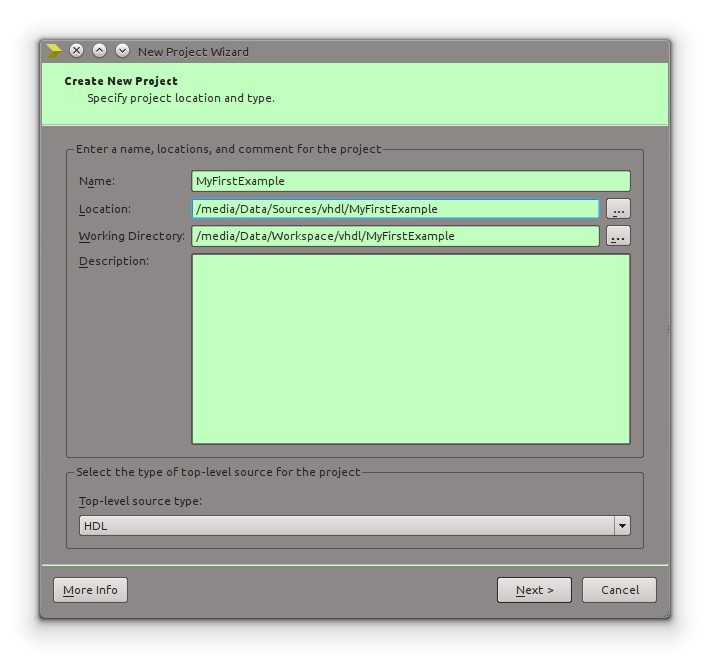
Note: the source files for the project and the files created by the ISE application do not have to be kept in the same folder as shown in figure 1 above.
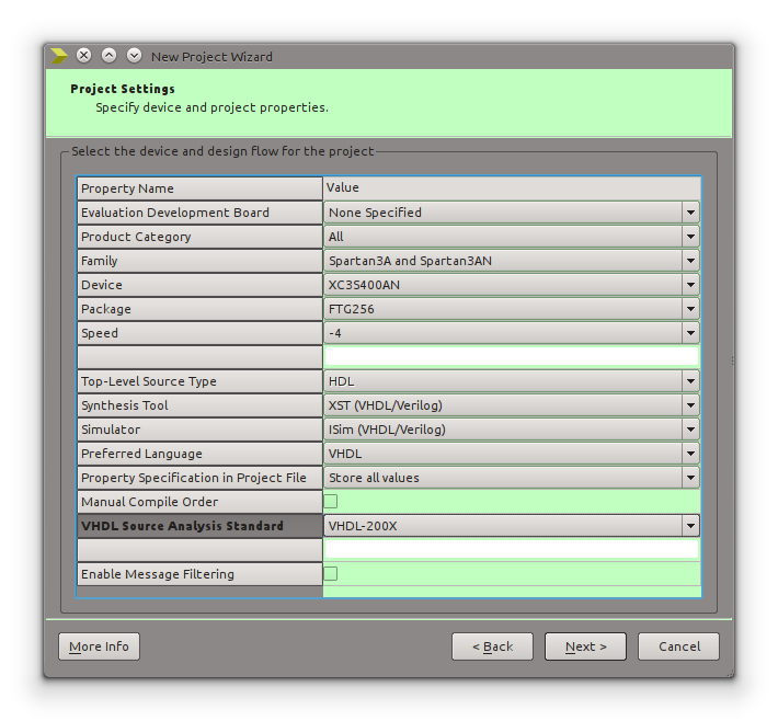
Clicking the Next button brings you to the Project Settings form where you need to select the right device, in our case select:
Family: Spartan 3A and Spartan 3AN
Device: XC3S200AN or XC3S400AN depending on which module you are developing for.
Package: FTG256
Speed: -4
Optionally you can change the VHDL Source Analysis Standard to VHDL-200X
See figure 2 for a visual representation of the expected form once set.
Clicking Next will bring the Project Summary window where you can check that the values selected are as expected and clicking Finish will close the New Project Wizard and bring you back to the ISE main window.
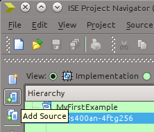
Now we need to add some source files to the project. We do this by selecting Project>>Add Source... option in the main menu of the ISE Project Navigator window or clicking on the icon with a green + sign located near the Hierarchy window.
If the source files for the example are in the /Sources/MyFirstExample/ directory they will appear in the Add Source window. Otherwise you can either move them to the directory or navigate to wherever they are. Select them all (.vhd and .ucf files) and click on Open.

The Adding Source Files window appears showing the selected files with their Association set to All for the .vhd files and Implementation for the .ucf.
One of the source vhdl file is, however, a test bench and as such is only valid for simulation. To correct that change the field for aes220_MyFirstExampleTestBench-x.vhd to Simulation.
Simulating your first example
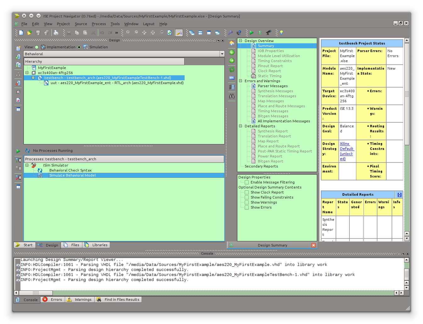
In order to simulate the example select the Simulation view and in the hierarchy window select the testbench. In the process window double click on the Simulate Behavioral Model to launch the simulation.
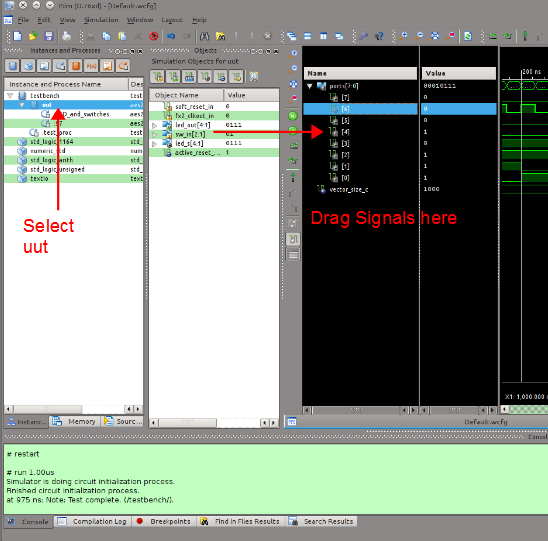
The simulator (ISim) will open in a new window and simulate the design according to the testbench. Note that the testbench in that example is only one example of the way of writing a testbench using a test vector file (see test_vector.tv) and displaying messages in the Console window at the bottom of the ISim window. The signals appearing in the graph window are the ports declared in the testbench. They can easily be renamed in the graph window (using F2 or double clicking on the name) or it is possible to simply drag the signals from the Objects window (select uut first in the Instance and Processes window) to the graph window.
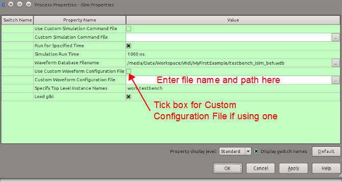
Note that you can save your setup either as the default configuration file (Default.wcfg) or with a name of your choice in which case you need to set the property in the ISE Project Navigator window.
Implementing your first example
Once the example has been simulated and is working according to expectation the next stage is to implement it. That is we will now compile the program into the configuration file to be downloaded into the FPGA. Before we do so we however need to modify our example. In order to see the LED flashing we have to change the frequency at which they do so. Open the MyFirstExample.vhd file and comment out line 67:
if count_v = 2 then
and uncomment line 68:
if count_v = 16777215 then
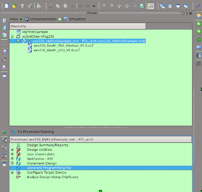
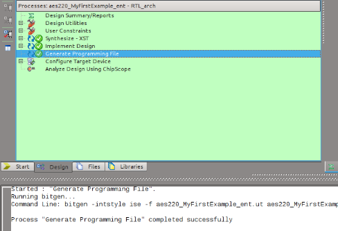
In the ISE Project Navigator window select the Implementation view. Then select Generate Programming File in the Processes window and either right click on it to select Process Properties (or select Process>>Process Properties in the main ISE Project Navigator menu).
In the Process Properties window tick the Create Binary Configuration File option as it the file format required by the aes220programmer software to configure or program the FPGA.
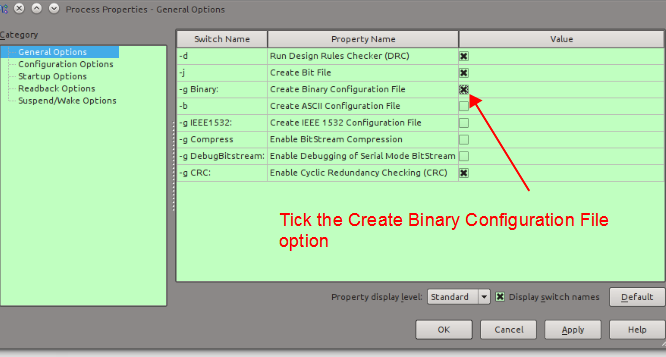
Now click OK to shut the window and double click on Generate Programming File in the Processes widow to start the compilation.
If everything goes well you will end up with 3 green ticks for the Synthesize – XST, Implement Design and Generate Programming File fields. If so congratulations! You are now ready to download the configuration file into the FPGA.
Configuring the FPGA
Connect the aes220 module to the USB port of the PC.
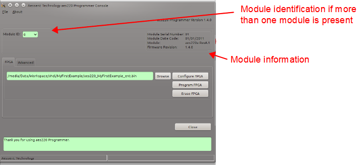
Open the aes220 programmer. The module serial number and other information should be displayed on the top right part of the window in the module information frame. If more than one module is plugged into the PC you can select through them using the Module ID on the left side of the module information frame. The Module ID will increment automatically, starting from 0, with each new module plugged in.
Browse to the binary file just created, which should be in the working directory selected when creating the project and click on Configure FPGA.
Once the configuration file is downloaded into the FPGA it will start running automatically. This is indicated by the DONE LED (D7) lighting up. Also the example will light the LED D1, D2, D3 and D4 in a counter clockwise manner. Pressing switch SW2 will change the flashing direction and pressing switch Sw1 will set the direction back to counter clockwise.
What we have done here is configuring the FPGA. However a FPGA needs configured each time it starts up. If we want the FPGA to start up in a particular configuration we need to write this one to the Flash memory inside the FPGA.
Note: internal Flash memory is a feature of the particular FPGA used on the aes220 module as a FPGA normally requires an external device to store the configruration binary.
To do that we simply click on Program FGPA instead of Configure FPGA. The configuration file will then get written to the Flash memory and the FPGA will get reset and start up with the configuration file present in the Flash.
Note: the FPGA will start up with the configuration file present in the Flash memory each time power is applied to the board, either via the USB port or one of the Vin input on connectors P1 or P2.
There is no need to use the Erase FPGA function. The Flash memory can be reprogrammed without erasing the memory first which reduces the numbers of write cycles to the Flash. It is also possible to load a different configuration file into the FPGA without modifying the one present in the Flash memory. Obviously if the module is reset it is then the configuration file present in the Flash that will be loaded.
Checking the example:
Once the configuration file has been downloaded into the device it will start running automatically. The four LED D1 to D4 will start flashing in a counter clockwise fashion. If they appear to be all on at the same time it is probably that line 68 in the aes220_MyFirstExample.vhd file is still commented out (and line 67 is not).
If everything is fine and the LED are flashing as expected in a counter clockwise fashion then pressing switch 1 (SW1) will make the LED flash in the other direction. To get the LED to flash counter clockwise again press switch 2 (SW2).
Et voilà!